


Navisworks is an advanced BIM software that allows precise coordination between the fields of construction. Up to now, there have been more than tens of thousands of users, with a few key functions such as Model Aggregation, Simulation & Animation, Quantification,… In which, Clash Detection is one of the core functions that Navisworks focuses on developing.
Understanding clash detection
When clashes occur, your construction plan will inevitably fall, cost and time will increase many times. Therefore, for the construction process to take place effectively, you must always resolve all those clashes before starting construction on site.
The clash detective tool allows you to identify, test, and report bottlenecks in the 3D model, helping to avoid unexpected mishaps and keep the project running smoothly. When you finish the design, you can use this tool again to ensure the accuracy of the project. Or can be used as an ongoing audit check of the project.
Clash Detection in Navisworks
Navisworks has 3 functions that make it a favorite BIM software, which are Clash detection, Model aggregation, Analysis & Simulation. In which, Clash detection is one of its most pre-eminent functions.
There are 3 types of clashes:
1. Soft Clash
Soft Clash is a conflict where elements are not given geometrical or spatial tolerances and their buffers are violated. For example, designing a ventilator will require a certain number of holes or openings for installation, maintenance, and safety. But in that place it was negated by beams.
2. Hard Clash
As the name suggests, this is a type of “hard” Clash that if they were only discovered at the construction site, would take a lot of time and money to fix. When two large elements intersect or pass through each other. For example, a pipe through a beam.
3. Workflow Clash
Workflow Clash is an element of planning conflict. In this type of clash, Navisworks helps us to find out what went wrong in our planning and to be able to quickly fix it. For example, construction takes place before the delivery of materials,… Also, it is called 4D Clash.
These clashes must be handled thoroughly and promptly to avoid affecting the schedule of the project as well as other disciplines.

Clash Detection in Navisworks – Step by Step Workflow
The best solution we found is to combine all 3 software Revit, Navisworks and Revit Plugin.
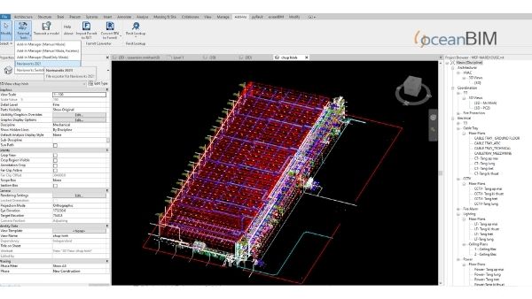
Step 1. Create NWC and NWF files in Navisworks
Create three 3D views in Revit. This makes it simpler to perform noise checks, without the need to filter or create any kind of set. Then directly load the two exported NWC from Revit, select both and do the test, and finally save the file as an NWF. Once done, we will have three NWF files: Ventilation/Pipe, Ventilation/Tray and Pipe/Tray.
Step 2. Indicate the intersection points by creating the Revit line.
Use a Revit file to point out clash points. This file will store the shared parameters that we will use in the clash analysis.
At this point, more parameters are shared to tailor it to the workflow. You can use filters when reviewing and resolving clashes.
The Revit Plugin automatically populates the “Clash_Date” and “Clash_Name” fields. To be able to filter clashes by date and analysis have done: ventilation vs pipe, ventilation vs tray or pipe vs with tray.
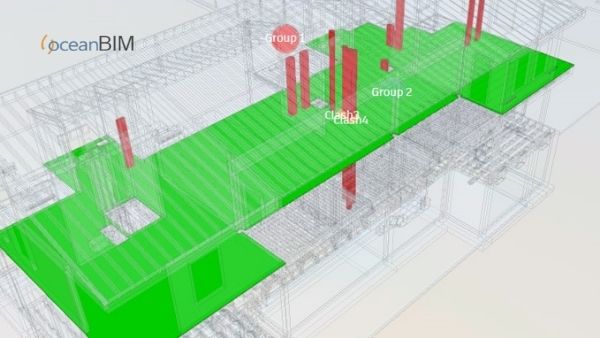
The field “Clash_Group” allows grouping effects by selecting them directly from the 3D view and grouping them by different criteria: specialization, level, volume, etc. Much simpler and more graphical than Navisworks, as it can be done directly from Revit’s 3D view.
“NEW” is entered as the default state. When working, you need to change the state and add the information of each state to apply the view filter. Color the areas that have done, are doing and have not done to make the work process smoother.
Clash’s statuses
NEW: Default state, which means it’s unprocessed.
ACTIVE: Under revision and no solution yet. Clashes in this state are pending. For these state of clashes, we must add a comment in the “Clash_Comments” field.
APPROVED: Reviewed and approved. We need to add comments in the “Clash_Approved by” and “Clash_Comments” fields.
IS NOT: Considered and not affected at the construction site.
RESOLVED: Resolved. For these state of clashes, we must describe what we do in the “Clash_Comments”, “Clash_Approved” field: who approved and.
It is reviewed and has been resolved. In “Clash_Comments” we have to add a description of what was done, “Clash_Layout“ to edit the plans that these clashes affect.
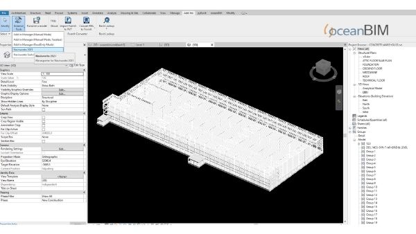
Step 3. Create a Revit model with conflicting points
First, add the generated file group name to signal noise.
Note: Check if it has the same units as the base model. Check if the view is “True North”.
Then save and launch the Dynamo script.
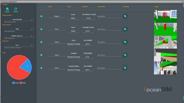
Step 4. Run Revit Plugin.
Repeat this process for three interference tests, all clashes will be shown in Revit.
Step 5. Apply view filter.
Inserting shared parameters and applying views is an iterative and slow process. Speed it up using a script, or create a new Revit project then insert the shared parameters. Once that’s done, create a schedule with all parameters shared, save, and close.
Then go back to the base project and what we need to do is insert the shared schedule and parameters at the same time. Finally create filters by states, using shared parameters and setting colors to identify them.
Conclusion
Resolving clashes is a very important part of the project. To detect and resolve clashes, you must work with experts to come up with the best solutions.
Connect with our oceanBIM experts at https://oceanbimcloud.com/clash-detection-services for 24/7 support with BIM services.